
BST SERIES CAM CLUTCHES
BST SERIES CAM CLUTCHES
BSTSERIES CAM CLUTCHES
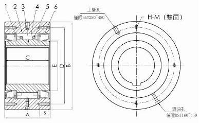
1. Baffle 2. Outer ring 3. Inner ring 4. Cam 5. Spring 6. Oil seal
Other introductions:
Size and performance
| Model | Torque Capacity | Max.Overruning Lnner Race(r/min) | Bore Dia.Range | A | B | C | D | E | S | H-M Threaded hole H-MNO.of Tapped Holes×Side×Pitch | Weight(kg) |
| BST 30 | 294 | 200 | 20~30 | 64 | 90 | 64 | 80 | 45 | 13 | 4×M6×P1.0 | 2.1 |
| BST 50 | 784 | 200 | 30~50 | 67 | 125 | 67 | 110 | 70 | 16 | 4×M8×P1.25 | 4.0 |
| BST 65 | 1570 | 150 | 40~65 | 90 | 160 | 85 | 140 | 90 | 20 | 6×M10×P1.5 | 11.5 |
| BST 75 | 2450 | 150 | 50~75 | 90 | 170 | 85 | 150 | 100 | 20 | 6×M10×P1.5 | 13.1 |
| BST 85 | 5880 | 150 | 60~85 | 115 | 210 | 110 | 185 | 115 | 30 | 6×M12×P1.75 | 24.7 |
| BST 95 | 7840 | 150 | 70~95 | 115 | 230 | 110 | 200 | 130 | 30 | 6×M14×P2.0 | 29.4 |
| BST 110 | 10800 | 150 | 80~110 | 115 | 270 | 110 | 220 | 150 | 30 | 6×M16×P2.0 | 34.2 |
| BST 135 | 15700 | 100 | 90~135 | 135 | 320 | 130 | 280 | 180 | 30 | 8×M16×P2.0 | 68.0 |
| BST 160 | 24500 | 100 | 100~160 | 135 | 360 | 130 | 315 | 220 | 40 | 10×M20×P2.5 | 85.6 |
| BST 200 | 37200 | 100 | 100~200 | 150 | 430 | 145 | 380 | 265 | 40 | 8×M22×P2.5 | 140.0 |
| BST 220 | 49000 | 80 | 150~220 | 235 | 500 | 230 | 420 | 290 | 40 | 16×M20×P2.5 | 263.5 |
| BST 250 | 88200 | 50 | 180~250 | 295 | 600 | 290 | 530 | 330 | 50 | 16×M24×P3.0 | 580.0 |
| BST 270 | 123000 | 50 | 200~270 | 295 | 650 | 290 | 575 | 370 | 50 | 16×M30×P3.0 | 620 |
| BST 300 | 176000 | 50 | 230~300 | 295 | 780 | 290 | 690 | 470 | 60 | 16×M30×P3.5 | 850 |
| BST 335 | 265000 | 50 | 250~335 | 305 | 850 | 320 | 750 | 495 | 70 | 16×M36×P4.0 | 1135 |
| BST 350 | 314000 | 50 | 250~350 | 320 | 930 | 360 | 815 | 535 | 70 | 16×M36×P4.0 | 1605 |
| BST 425 | 510000 | 50 | 325~425 | 440 | 1030 | 450 | 940 | 635 | 70 | 18×M36×P4.0 | 2450 |
| BST 450 | 686000 | 50 | 350~450 | 450 | 1090 | 480 | 990 | 645 | 80 | 18×M42×P4.5 | 2820 |
Installation and use
Used to prevent the reversal of conveyor belts or pumps during low-speed operation.
Before installation, confirm that the rotation direction of the inner ring of the BST cam clutch (indicated by the arrow on the inner ring) is consistent with the rotation direction of the conveyor belt.
Use bolts of grade 11T or higher to securely install the force arm on the BST cam clutch. Please ensure that the surface of the force arm is aligned with the side of the outer ring and free from any dust.
The recommended tolerance for the shaft is level H7 or H8.
When installing the BST cam clutch onto the shaft, only apply pressure to the outer ring. Do not directly strike the inner ring or outer ring, dust seal, or apply any force on the dust end plate with a hammer.
When installing the cam clutch onto the shaft, a flat key should be used, and then the clutch should be fixed onto the shaft with an end plate. Under no circumstances should cone keys be used.
When installing BST cam clutch (grease lubricated type) of BST160 or above, place one of the four oil holes directly at the bottom. This method facilitates the leakage and cleaning of lubricating grease.
When the shaft rotates, the end of the lever arm will swing to certain positions in the direction of rotation. Only constrain the force arm in the direction of rotation, but ensure that the force arm has a certain amount of space to swing freely. If force
If the end of the arm is completely fixed, the inside of the clutch will be twisted, which will cause damage to the components.
The force arm of the BST series cam clutch is standardized.

| 
Scan Follow |
© 2024 Stdier Transmission Technology (Xiamen) Co., Ltd. All Rights Reserved.