
PB SERIES CAM CLUTCHES
PB SERIES CAM CLUTCHES
PB SERIES CAM CLUTCHES
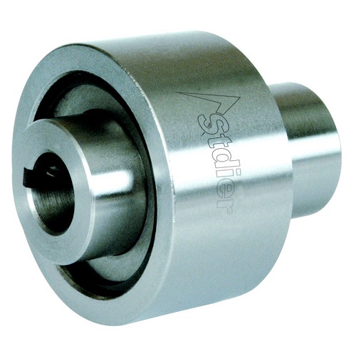
1. Sleeve 2. Outer ring 3. Spring 4. Cam 5. Lubricating oil plug 6. Baffle 7. Collar 8. Positioning screw 8. Inner ring
Other introductions:
Size and performance
| Model | Torque Capacity | Max.Overrunning | Max.Indexing(cycle/min) | Stock Bore Size | A | B | ||
| Inner Race | Outer Pace | Dia(H7) | Keyway | |||||
| PB3 | 29.4 | 1800 | 900 | 150 | 10 | 4×1.5 | 50 | 50 |
| PB5 | 147 | 1800 | 900 | 150 | 16 | 5×2.0 | 70 | 60 |
| PB6 | 382 | 1500 | 800 | 150 | 20 | 5×2.0 | 82 | 73 |
| PB8 | 568 | 1200 | 650 | 150 | 25 | 7×3.0 | 85 | 83 |
| PB10 | 843 | 1000 | 400 | 150 | 31.5 | 10×3.5 | 92 | 95 |
| PB12 | 1530 | 800 | 300 | 150 | 40 | 10×3.5 | 100 | 113 |
| PB14 | 2110 | 700 | 300 | 150 | 45 | 12×3.5 | 112 | 133 |
| Model | C(h7) | D | E | F | G | Stock Bore Size | Lubrication | |
| K | L | |||||||
| PB3 | 23 | 22 | 25 | 21 | 25.7 | 4×2.5 | 16 | M6×P1.0 |
| PB5 | 32 | 32 | 35 | 25 | 38.8 | 5×3.0 | 20 | M6×P1.0 |
| PB6 | 38 | 38 | 37 | 33 | 41.0 | 5×3.0 | 27 | M6×P1.0 |
| PB8 | 45 | 40 | 45 | 33 | 42.0 | 7×4.0 | 27 | M6×P1.0 |
| PB10 | 60 | 41 | 60 | 37 | 44.0 | 1O×4.5 | 28 | M6×P1.0 |
| PB12 | 65 | 50 | 66 | 37 | 52.6 | 1O×4.5 | 29 | M6×P1.0 |
| PB14 | 75 | 54 | 76 | 41 | 57.3 | 12×4.5 | 30 | M6×P1.0 |
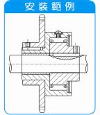
Installation and use
The coaxiality between the outer and inner rings of the PB series cam clutch is maintained through a sliding bearing between the outer ring and the shaft, which can also withstand radial loads acting on the outer ring.
The recommended tolerances are listed below.
| Model | Public errand |
| PB3,PB5,PB6,PB8 | 0 to -0.013 |
| PB10,PB12,PB14 | 0 to -0.016 |
Do not use the PB series clutch as a coupling, instead use a more elastic connector for shaft connection.
The arrow on the end face of the clutch indicates the direction of rotation of the clutch. Please confirm if the direction of rotation is correct before use.
When the clutch is used for positioning purposes, please lubricate it with oil.
The keys used should comply with JIS B1301-1959 standard.
Please use other devices to withstand thrust loads and do not directly apply them to the cam clutch.
The hole tolerance of the driven components such as the key wheel on the clutch outer ring should comply with the H6 or H7 level requirements of JIS standards.
| 
Scan Follow |
© 2024 Stdier Transmission Technology (Xiamen) Co., Ltd. All Rights Reserved.