
TFS(TFS12-TFS80) SERIES CAM CLUTCHES
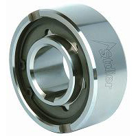
TFS(TFS12-TFS80) SERIES CAM CLUTCHES
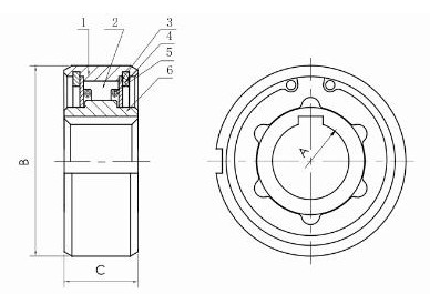
1. Outer ring 2. Cam 3. Barrier 4. Elastic barrier 5. Spring 6. Inner ring
Other introductions:
Size and performance
Max.Overrunning Speed | Inner | Outer | A | B | C | D | E | F | G | H | ||||
Model | Torque Capacity | Inner Race | Outer Race | Bore Size | Keyway | Weight | ||||||||
N.m | R/min | r/min | H7 | g | ||||||||||
TFS12 | 18 | 4,500 | 2,300 | 12 | 4x1.8 | 13 | 35 | 30 | 18 | 0.6 | 0.3 | 4 | 1.4 | 68 |
TFS15 | 28 | 3,500 | 1,800 | 15 | 5x1.2 | 18 | 42 | 36 | 22 | 0.8 | 0.3 | 5 | 1.8 | 120 |
TFS17 | 50 | 3,200 | 1,600 | 17 | 5x1.2 | 19 | 47 | 38 | 22 | 1.2 | 0.8 | 5 | 2.3 | 150 |
TFS20 | 84 | 2,500 | 1,300 | 20 | 6x1.6 | 21 | 52 | 45 | 27 | 1.2 | 0.8 | 6 | 2.3 | 220 |
TFS25 | 128 | 2,000 | 1,000 | 25 | 8x2.0 | 24 | 62 | 52 | 35 | 1.2 | 0.8 | 8 | 2.8 | 360 |
TFS30 | 200 | 1,600 | 800 | 30 | 8x2.0 | 27 | 72 | 62 | 40 | 1.8 | 1.0 | 10 | 2.5 | 530 |
TFS35 | 475 | 1,400 | 700 | 35 | 10x2.4 | 31 | 80 | 70 | 48 | 1.8 | 1.0 | 12 | 3.5 | 790 |
TFS40 | 607 | 1,300 | 650 | 40 | 12x2.2 | 33 | 90 | 78 | 54.5 | 1.8 | 1.0 | 12 | 4.1 | 1050 |
TFS45 | 756 | 1,100 | 550 | 45 | 14x2.1 | 36 | 100 | 85.3 | 59 | 1.8 | 1.0 | 14 | 4.6 | 1370 |
TFS50 | 1,124 | 1,000 | 500 | 50 | 14x2.1 | 40 | 110 | 92 | 65 | 1.8 | 1.0 | 14 | 5.6 | 1900 |
TFS60 | 1,975 | 840 | 420 | 60 | 18x2.3 | 46 | 130 | 110 | 84 | 2.6 | 1.5 | 18 | 5.5 | 3110 |
TFS70 | 2,514 | 750 | 380 | 70 | 20x2.7 | 51 | 150 | 125 | 91 | 2.6 | 1.5 | 20 | 6.9 | 4390 |
TFS80 | 3,924 | 670 | 340 | 80 | 22x3.1 | 58 | 170 | 140 | 100 | 2.6 | 1.5 | 20 | 7.5 | 6440 |
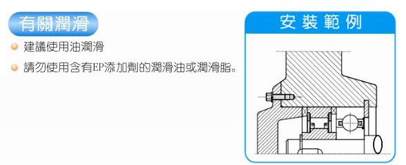
Installation and use
The outer ring and bracket of the TFS series cam clutch are designed in a press fit manner. The accuracy of surface dimensions must be ensured.
When the inner diameter of the bracket has a tolerance of H7 level, a key needs to be installed on the outer ring; When the inner diameter of the bracket is K6 level tolerance, there is no need to install keys on the outer ring.
Please ensure that the bracket has sufficient strength to withstand the pressure required for installing the cam clutch.
Please install the cam clutch in the direction indicated by the arrow on the cam clutch.
When installing a cam clutch, 62 type bearings should be used for assembly to avoid axial force, as these types of clutches do not have bearings installed inside.
The recommended tolerance for the shaft is grade H7.
Features of TFS series cam clutch: The foreign key groove is located on the end face of the outer ring.
| 
Scan Follow |
© 2024 Stdier Transmission Technology (Xiamen) Co., Ltd. All Rights Reserved.